
ENCLOSURE
Week 04 | 09/23/2022
A Case for Ultrasonic Distance Sensor
Enclosures are always fun to make, especially the ones that are designed for one’s own projects. The best part of each well-thought enclosure is its uniqueness, in my opinion.
This week, I customized a container / protector for one of my Physical Computing projects — an ultrasonic distance sensor, mounted on a breadboard, along with a LCD display, and of course, an Arduino, a switch, and some wires. Since it is a distance sensor, the mobility and stability of it should be high — so I also made it a detachable moving bed, with four caster wheels.
The project started with an extremely messy breadboard, with wires everywhere and LCD display and battery randomly placed on it. I spent a few hours tidying the breadboard by shortening and relocating some wires. The plan was to make a protector that has four sides open by using standoffs, hence increasing the ease of switching out parts later. Since mobility plays such an important role in a distance sensor, therefore a battery is needed. Battery is placed right next to the breadboard and it can be switched easily. All the wires are precisely measured, elegantly cut and bent afterwards, in order to make it look as tidy and simple as possible. One can easily read how the current flows — in my humble opinion, this model, in some way, might be more understandable and logical than a schematic diagram, since once can see what is really happening — direct visualization always helps.
The dimensions of the breadboard and battery are measured by a digital caliper, then a piece of holder is cut to stabilize them in x and y axes. Both the base and the holder are 1/4” acrylic, which I was lucky to find in the shop. The display and the toggle switch are screwed on the top. Thanks to the digital caliper and laser cutter, I was able to make the openings just fit. The caster wheels I bought are not the most ideal ones. Originally I was trying to put them on a base which shares the same dimension as the holder, then I found it could easily tip over due to how narrow the base is. So I updated the base and made it wider, meanwhile the screws can help position the bed.


figure 1 - original setup: power from a usb
figure 2 - upgraded setup: power from a 9V battery

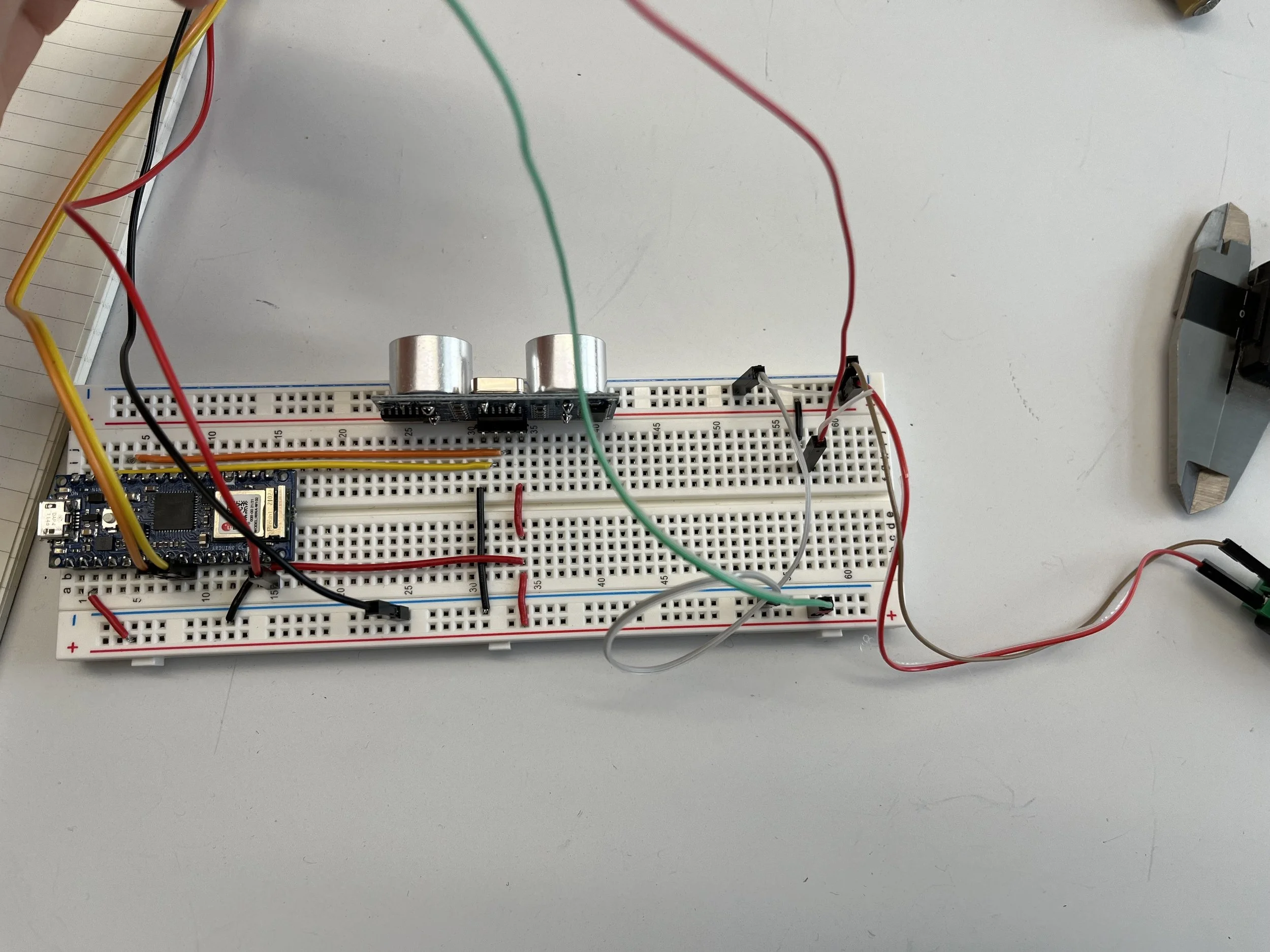
figure 3 - process of tidying
figure 4 - testing different outlet positions


figure 5 - holder is cut, standoffs are installed
figure 6 - battery can be easily swapped out


figure 7 - testing toggle switch and display
figure 8 - top is cut, switch and display are on


figure 9 - ready to work on the wires for the display
figure 13 - the piece is finally assembled
figure 19 - wheels are too close to each other
figure 10 - perspective view I before moving on
figure 14 - details
figure 20 - it worked, but not ideal


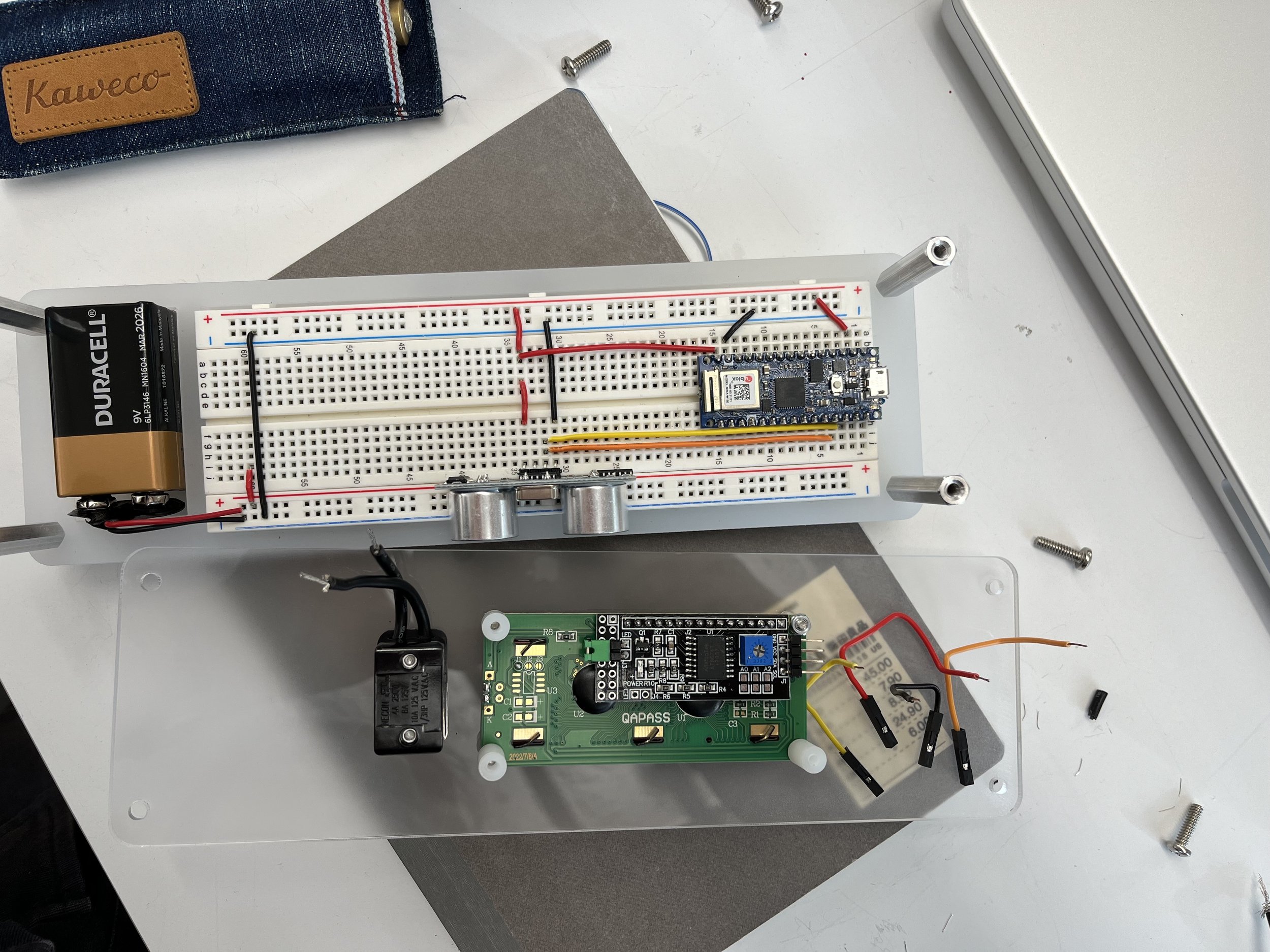


figure 11 - perspective view II before moving on
figure 15 - details
figure 17 - details
figure 21 - upgraded base — wider, same length
figure 23 - final product
figure 12 - wires for the switch and display cut
figure 16 - details
figure 18 - original idea for wheels
figure 22 - screws can help to position and stabilize the holder
figure 24 - final product
This project truly took me some time and a lot of brainpower, however I sincerely enjoyed the process and the outcome. Personally, I think this is one of the best projects I have ever made, including the ones from architecture school. If time permits, I would like to discover more about different tools and ways to customize containers and make my projects more complete.