TAVERN
An enclosure for Ultrasonic Distance Sensor
Fall 2022
Course: Fabrication
Instructor: Ben Light
Introduction
Creating enclosures is always an enjoyable task, especially when they are designed for one's own projects. The most unique and interesting aspect of a well-thought-out enclosure, in my opinion, is its distinctiveness.
For this particular project, I crafted a custom container/protector for one of my Physical Computing projects. It houses an ultrasonic distance sensor mounted on a breadboard, accompanied by an LCD display, an Arduino, a switch, and various wires. As it's a distance sensor, both mobility and stability are crucial considerations. Therefore, I designed it with a detachable moving bed equipped with four caster wheels.
Process
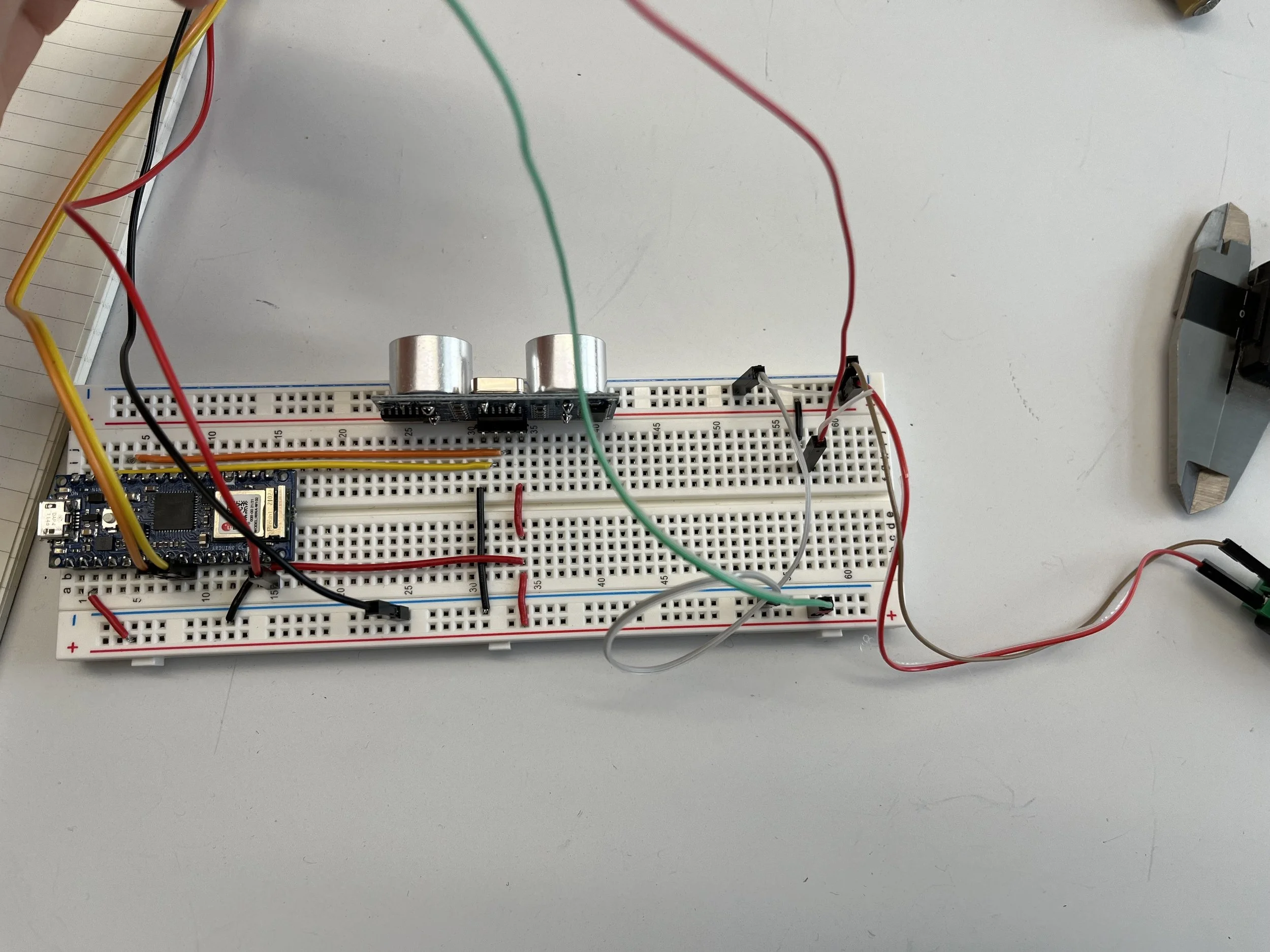
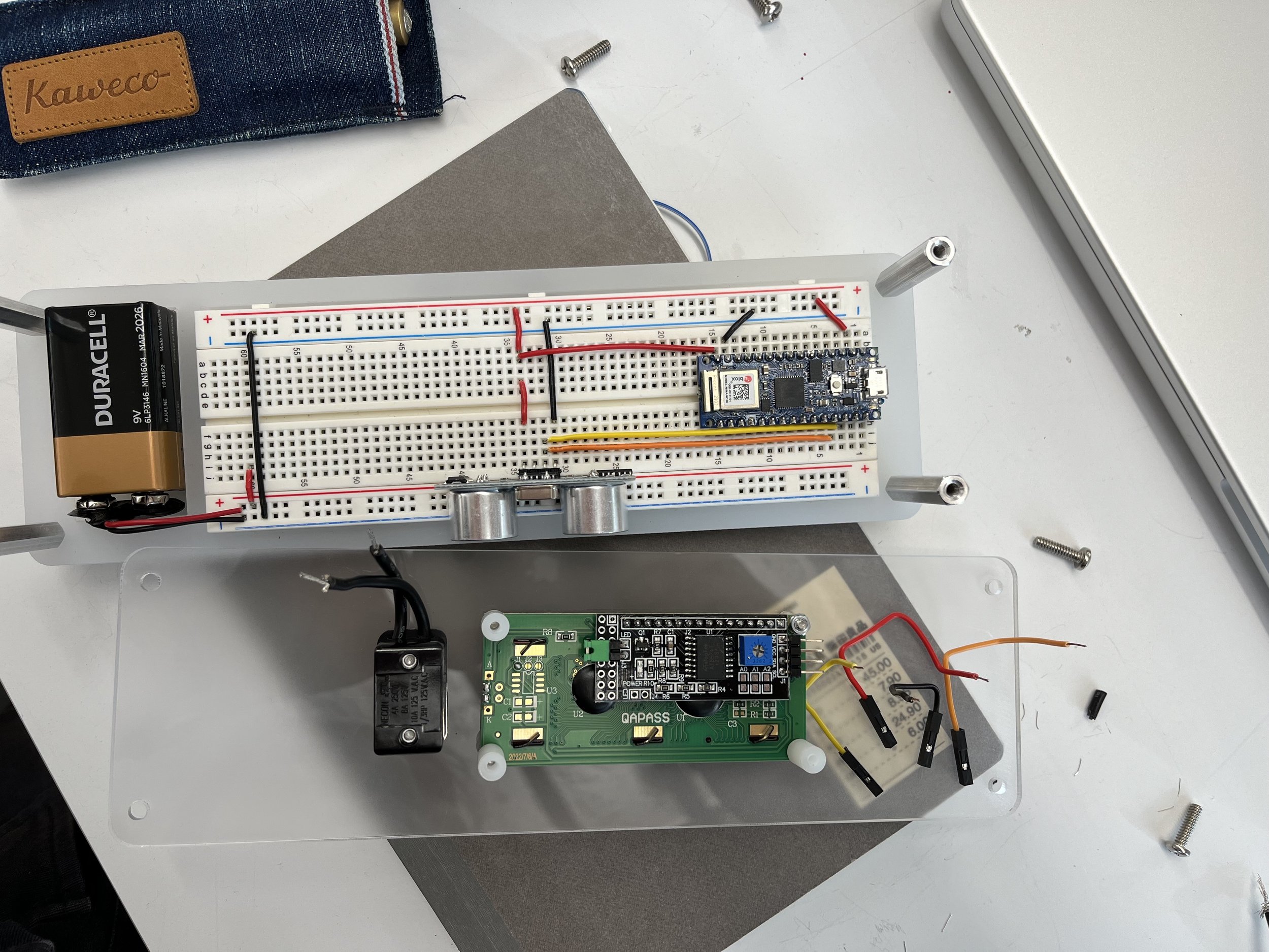
The project commenced with a chaotic breadboard, wires sprawling everywhere, and components like the LCD display and battery haphazardly placed. I dedicated several hours to organizing the breadboard, strategically shortening and repositioning wires. The objective was to design a protector with four open sides, utilizing standoffs for increased accessibility to switch out parts in the future. Given the significance of mobility for a distance sensor, a battery was incorporated, conveniently positioned next to the breadboard and easily switchable. Each wire was meticulously measured, elegantly cut, and bent to maintain a tidy and straightforward appearance. The visual representation of current flow in this model, in my opinion, might be more comprehensible and logical than a schematic diagram—direct visualization always aids understanding.
The dimensions of the breadboard and battery were measured using a digital caliper, and a holder was cut to stabilize them in the x and y axes. Both the base and the holder are made from 1/4" acrylic, a fortunate find in the shop. The display and toggle switch are securely fastened on top, with the digital caliper and laser cutter ensuring precise fittings. The caster wheels, while not the most ideal initially, underwent adjustments. Originally, I attempted to place them on a base with the same dimensions as the holder, but it was prone to tipping due to its narrow width. Consequently, I widened the base and utilized screws to secure the bed in position.
figure 1 - original setup: power from a usb
figure 2 - upgraded setup: power from a 9V battery
figure 3 - process of tidying
figure 4 - testing different outlet positions
figure 5 - holder is cut, standoffs are installed
figure 6 - battery can be easily swapped out
figure 7 - testing toggle switch and display
figure 8 - top is cut, switch and display are on
figure 9 - ready to work on the wires for the display
figure 13 - the piece is finally assembled
figure 19 - wheels are too close to each other
figure 10 - perspective view I before moving on
figure 14 - details
figure 20 - it worked, but not ideal
figure 11 - perspective view II before moving on
figure 15 - details
figure 17 - details
figure 21 - upgraded base — wider, same length
figure 23 - final product
figure 12 - wires for the switch and display cut
figure 16 - details
figure 18 - original idea for wheels
figure 22 - screws can help to position and stabilize the holder
figure 24 - final product
Conclusion
This project demanded a significant investment of time and intellectual effort, yet I genuinely relished the entire process and the resulting outcome.


